
SG32.1000SMT Surge Generator
SKU: SG32.1000SMTThe SG32.1000SMT includes the following tests:
- ARC Multi-shot: The Arc Reflection
- Method overlays and compares a low voltage reference trace and a high voltage fault trace captured via capacitor discharge through an inductive (coil-type) filter.
- 8 comparative measurements per ARM shot are displayed (Multi-shot feature), and the results are evaluated automatically.
- ICE/Surge Pulse: After fault ignition via capacitor discharge, the Impulse Current or Surge Pulse method measures the current component of the travelling wave, This technique is suitable for long cables and PILC cables.
- DECAY: After fault ignition via HV DC source, the DECAY method measures the voltage component of the travelling wave. This technique is suitable for very long cables, HV transmission cables and faults with very high breakdown voltage.
- IFL: Intermittent Fault Locating; to find intermittent faults with temporarily changing characteristics like they often occur in street lighting systems.

Description
Key Features:
- 1-inch full-color TFT touch screen;
- Embedded system, safe, stable, simple display and operation mode;
- With the function of testing cable wave velocity, cable length and fault distance;
- Fully automatic continuous sampling, waveform capture at all times, timely and accurate.
- With automatic test range setting, automatic waveform analysis and display of test distance.
- English menu, touch and coding button two operation modes, simple, fast and reliable.
- With low-voltage pulse method, high-voltage flashover method, multiple pulse method (8 times) test technology, waveform display is smooth and easy to read.
- When using the multiple pulse method, it is used with a pulse coupler to display 8 groups of high and low voltage waveform comparisons, which is convenient for automatic test distance, manual analysis and distance measurement.
- The instrument has powerful data processing capabilities, which is convenient for users to manage and archive waveform files.
- It has a massive test waveform storage function: the waveforms tested on site can be conveniently stored in the instrument in the order specified by the Chinese naming regulations, so that they can be called up for observation and analysis at any time; it can store more than 8,000 low-voltage pulse and high-voltage flashover waveform records, and more than 250 multiple pulse waveform records. The waveform files can be imported into the computer software for management and analysis using USB communication.
- Ultra-high brightness, LED backlight brightness up to 280nit, resolution 1024*600, easy to operate in direct sunlight.
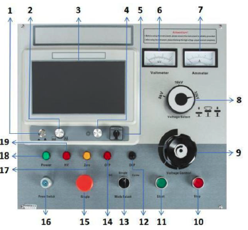
1 Switch: Turn on/off the working power;
2 Amplitude: When collecting waveforms, adjust the amplitude knob to change the amplitude of the collected waveform.
3 Display: 10.1-inch full-color TFT touch screen.
4 Operation knob: Rotary button for system interface operation control, rotate to select and press to confirm;
5 Mode selection: Low Voltage Pulse: Low voltage pulse method; HV Flash: High voltage flashover method; Multiple Pulse: Multiple pulse method;
6 Voltmeter: High voltage output voltage indication kV meter, divided into 8kV, 16kV, 32kV combined with voltage level switch reading.
7 Ammeter: Indication of current size.
8 Voltage rotation mode (Voltage select): This key has three voltage level modes, 8kV, 16kV, 32kV. Please rotate to the appropriate position before turning on the machine. Lift, rotate, and press.
9 Voltage control knob: When this knob is in the zero position, the zero position light is on and the high voltage can be started. The voltage can be increased only after the high voltage is started.
10 Stop button: When the test is completed or an abnormality occurs, press this button to cut off the high voltage output, and the remaining high voltage of the test will be automatically discharged.
11 Start button: In the zero position, press the start button, the high voltage starts, and the high voltage light is on. In the non-zero position, the high voltage light is not on.
12 Overcurrent protection switch (OCP): When pressed, the overcurrent protection function has started; when it pops up, it means that the instrument has triggered the overcurrent protection.
13 Mode select: It is divided into three modes: withstand voltage (DC), single, and cycle. DC is the withstand voltage function. When this function is selected, the cable will be subjected to withstand voltage test; Single is a manual function. When this function is selected, the high voltage will be started and then boosted. Pressing the Single key can manually trigger the impact discharge; Cycle is an automatic function. When this function is selected, the high voltage will be started and boosted. The instrument will automatically trigger the impact discharge for about 7 seconds.
14 Overheat indication (OTP): When performing multiple pulse method tests, this light will light up, indicating that the internal temperature of the instrument is too high. Please stop using the multiple pulse method test.
15 Single key (Single): When the mode selection key is in the Single function, this key is valid.
16 Power switch (Power Switch): Turn clockwise to turn on the system power supply, and counterclockwise to turn off the system power supply.
17 Zero position light (Zero): Indicates that the voltage adjustment knob is in the zero position state. The high voltage can only be started when the zero position light is on.
18 Power light (Power): When the power switch is turned on, the indicator light is on.
19 High-voltage light (HV): When it is on, it indicates high-voltage output; when it is off, it indicates no high-voltage output.
Content missing